Saturday 27 February 2016

Weekly progress 22 - 26 February

I’m at a crucial point in my MA studies, with only a few months left till the degree show, I’ve taken some time off my part-time graphic design job to focus on my projects.

The plan for my 6 weeks off is to make goals each week and try smash them to move the project on to make it a reality, this post is a journal of what I got up to during week 1.

I'll add in a link here to a catch up on my Pinball Machine and Pinball Prints projects when I post them.

This week my basic goals were:

  • Complete wiring the pinball cabinet & powering up
  • Start accurately measured Playfield Design
  • Complete audio integration for the exchange project

Monday

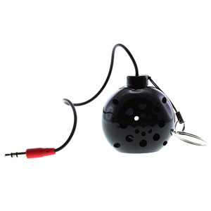
Bob Leadbeater of BLM Audio helping prototype an audio amplifier for a Raspberry Pi
Monday morning started focussing on my submission for a student exchange exhibition Read my post about that exchange project brief. The final piece is a hand made print with an embedded screen. I'm on schedule with the other parts of the project, now I am working on the audio.

With some valuable advice and collaboration with Bob Leadbeater we prototyped a small audio amplifier for the project. Unfortunately what we put together wasn't fully compatible with the Raspberry Pi, so I do more research and will revisit on Tuesday. Read more about integrating speakers into a Raspberry Pi Project.
Wiring up cabinet switches to a temporary connector
In the afternoon I moved my attention to the main event, the pinball machine. I'm getting my head around making the extra switches I need for the cabinet.

Carefully studying and deciphering the original pinball machine schematics - mapping to the software
These switches are for flipper buttons and the start as well as some other switches for control. This involves quite a bit of studying of the schematics from the donor pinball playfield 'Supersonic' (1979). Every problem I solve in this project, I am finding a new set of skills and heightened level of understanding. Taking it one step at a time makes the process easier.

Tuesday

Left to right: 48v supply (solenoids), ATX supply (for boards, switches, LEDs), MyPinballs Control Board, Driver Board with original playfield connections.
I've been a bit wary about connecting the higher power supply in fear of doing something wrong. Luckily MyPinballs has a dedicated hardware support forum to help with all aspects of the Custom Pinball Controller board sets, which he has kindly sponsored to my project. The group consists of Jim of MyPinballs along with everyone who owns the board set and are each working on their own custom pinball machines. A indispensable wealth of knowledge! 

Planning my very simple power board based on the original pinball machine connectors

This bank of knowledge is really useful for learning how to setup the boards and how to do a specific task, such as wiring up custom power supplies. I've started getting my head around it by drawing out diagrams, translating the information I have into a way I can understand it. Colour code helps, these old pinball schematics are all black and white!

Final audio setup and draft layout

In the meantime I'm quickly dropping back in on the exchange print project, and finalising the setup for audio. Read more about integrating speakers into a Raspberry Pi Project.

Installing LED bulbs in place of the original incandescents - it's a fiddly job!

To finish off the day I made a start to installing LEDs to the Supersonic playfield for testing. The original incandescent bulbs are not compatible with the boards, due to current pull.

Pretty satisfying to see some LEDs working. Testing 5v into the General Illumination


Wednesday

Most of today is dedicated to wiring up the pinball machine to my custom power supply. After carefully consulting the schematics I made a temporary power junction.

Temporary power junction connector
My desk! Pretty awesome right?
When powering up the LEDs all work fine, but the flipper solenoids seem to be stuck on full power for some reason. I check my wiring and get back to the online group to problem solve. Something isn't quite right with the solenoid driver power so I'm double checking the game code & asking group questions.

I still haven't been able to get my flipper buttons working so testing with the multimeter to try find the root of the problem. I believe it is a programming issue, but could be a mistake I have made with wiring.

Thursday

Production line!
I spent the morning in fabrication at uni, making alterations to frame two of my exchange exhibition prints. I basically need to build out the back of the frame in order to include a back panel to mount the Raspberry Pi, Screen and speaker.

At uni I had to opportunity to speak to the fellow MA Printmakers who will also graduate this year about a London exhibition I'm helping to organise in September.

Now a nice bike ride back to the studio for another evening trying to nail this power and flipper buttons problem. After sharing my current game coding with the group, Jim helped me find the source of both problems.

Good news first, with the flipper buttons: because I have an early release of the control boards, the direct switches are mapped to different pins on the Arduino. Thanks to the forward thinking of Jim, he had setup the files in such a way so all that required was to simple change the pin numbers in the pinball controller switch library. I can see flipper buttons in the log files. Is it wrong I'm excited about buttons working!?
The control board can be monitored by USB, great for problem solving!
Now the bad news. We had hoped solving the flipper buttons would solve my power board issue too, but unfortunately not. After a lot more testing we eventually figured out, at some stage, somewhere I had managed to fry two of the transistors on the driver board. I really don't know what I did, but I think something may have shorted, feeding 48v through my low power boards.

The power driver board and my two busted transistors closest - hard to tell without a multimeter

Here's my meter readings comparing the busted transistors to the working ones

I feel a bit silly for whatever caused the problem, but it sure is a learning curve. Although it has set me back getting the pinball machine playable, I've made some serious progress this week, and learned loads in the process.

Friday

Most of the day is spent catching up on some freelance work, keeping the admin side of working part time as a freelancer up to date - unfortunately due to the nature of working freelance I can't take holidays! Just now I have a few jobs on, including recurring work for Shetland Arts and Crafts Association and their annual Craft Trail & Members booklet for 2016/17. Also, another exciting project that is just in the sketching phase is a poster for Shetland College’s new BA Fine Art course.

I also made sure the new transistors were paid for so I can get on with replacing those early next week. In terms of completing my weekly set goals, although technically the pinball machine powered up and flipped, it wasn’t as intended so unfortunately that goal was unobtainable this week. The other thing that got left to the side was the playfield design, which ideally I want to have well underway next week. The evening was spent beginning to translate the playfield to a digital cutter template, for lasercutting my own playfield.

Carefully measuring key features of the playfield. Double checking. Triple checking. I'd love a set of callipers right now.
My measurements translated to a digital cutter file, with an early preview of some of my customisations to the original game
I'm a bit behind with this template now, but it's quite important to get it right and take my time. I've split the playfield into thirds, on Monday I plan to make progress on the middle and Tuesday or Wednesday I'll complete the top. The lower playfield looks like it will be the trickiest so hopefully I can make up time now.

It may have been noted that I’ve not been very good at sharing with you and documenting my progress on my pinball machine project. I really think this is due to the nature of it, many pieces have to come together at the right time in order for it to actually happen, I’ve perhaps been apprehensive about putting things out there and having big gaps in between updates and perhaps a slight fear of the whole thing not happening. I'm now at a point where I've made some serious progress so will continue progress updates, follow me on Instagram for more regular insights.

Tuesday 23 February 2016

Speaker audio output for Raspberry Pi project

I'm currently working on integrating speakers into my Raspberry Pi powered project. The project is a hand made print with an embedded screen, it is part of a student exchange exhibition between UWE, Bristol (UK) and MICA, Baltimore (USA). (Read my post about that project brief)

Due to how the Raspberry Pi is setup, it's not as simple as just plugging in a speaker as I had originally planned...

Plan A: USB Powered Speakers

So figuring out I need active (powered) speakers, my first plan was to use off the shelf USB powered computer speakers. I found some at Staples for around £5 - this is the top end of my budget really - so yes they will sound cheap!


There are many options on Ebay and Amazon - I'm sure further testing of different types of speakers would be advisable, most tell you the specs anyway, and are easy to take apart to fit your project.

The Adafruit speakers (pictured below) are supposedly picked to get the best audio from a Raspberry Pi. I've not used these and kept on the budget route anyway, sure the audio is going to sound raw as a result.


I'm trying to power the speakers directly from the onboard Raspberry Pi USB - my USB speakers did not work, all you could hear is the pulsing of power drawing from the PI - this is probably not good for it.


By default the maximum current all USB peripherals can draw from the USB port is 600mA - there is a way to increase it according to Hackaday. For my project, I need to check I can do this (as I also have a LCD screen). My power supply is 5v 2A, I may need to make it beefier, maybe 3A or 4A. Will hold off on this just now when I explore other options.

Plan B: Custom LM386 Audio Amplifier

Enlisting help from audio aficionado, Bob Leadbeater of BLM Audio (and my studio neighbour), we set about making a custom audio amp using the LM386 chip, with help from this instructables


After some serious prototyping our efforts weren't successful, we're pretty sure this is due to the levels of audio the rPi spits out.

Using components like they aren't designed to. Hack it
But of course many of the problems are me! Due to working on no budget, I'm hacking together cheap components and set on using the on board rPi USB as a power supply. This way of working is not good really, especially when working alongside a professional such as Bob (sorry Bob)!

Perhaps we're barking up the wrong tree...

Ceramic dog-shaper speakers design by Matteo Cibic.
...but I'm adamant to get it working via the USB power. Perhaps it's a no go, but as before maybe I need to try increasing the current to the USB ports.

For now I've realised the importance of having the audio, my absolute fallback is to use headphones. Proof of concept and for demonstration I need a working version, so on to Plan C...

Plan C: Battery Option

My next option was to get something up and running quickly. I found this portable bomb speaker, from Tiger for a whopping £4, is a rechargeable keyring meant to play music from devices. You can find crap like this anywhere, I only thought right now I may have been able to get something in the pound shop. 
When pulled apart it was easy to fit into my project. The 3.7v lithium-ion battery seems to charge fine directly from the Raspberry Pi USB. Playing and charging at the same time worked ok when I tested it. I'd like to leave it running for longer period of time to see what happens when the battery is flat. 

Add to CV: Pulling apart cheap speakers


I also tested completely cutting out the battery, the USB still powers the speaker. With and without the battery, I'm not trusting this setup in my project, plus it's dirty and horrible - looks and sound.

I'm not overly impressed with the quality and the use of a battery in my project. It might work for you but...
It sounds like shit...
Toilet Speakers. For playing all the songs you don't like

Plan D: Adafruit Stereo 2.8W Class D Audio Amplifier

I'm thinking I need to try an amp again, of course I can buy assembled boards online, I'd like to make sure I get the right one before I go ahead and found these Adafruit boards. Find it to buy here. There's also the 3.8W one. They have some cheap 4 Ohm 3 Watt speakers too, worth a try...

But hold on...

In the process of hacking different bits of speakers and amps along with researching online, I decided to give Plan A (USB powered speaker) another look as it is the simplest option for me. So just before altering the rPi to send more current to the USB hubs, I decided to try again. This time, with one of the speakers removed, the circuit worked fine, no stuttering and sound working as well as it can. The current draw with two speakers must have just been a bit much for the USB hub. 


The amp board on this particular set of speakers has a little volume control wheel and LED to show it is powered - this is quite handy for my project actually - I'll make an access hole on the back panel to allow alterations to sound levels.

I'm only looking for one speaker in my project. If you're looking for two you may need to try increasing the current to the USB hubs, for better quality and control try out the Adafruit amp - which was my next step.

I don't have much experience working with audio on projects, it is something I tend to neglect or leave till after the visuals, this process has made me realise it should be a much more important aspect of a project, well planned out from the very beginning.

Tuesday 16 February 2016

Student Print Exchange: Development

I had thought my initial concept would be too expensive for making an edition of six for the exhibition. I have now spec'd the project and it comes in at around £70 per print, which is almost double my initial expectations.

I had thought of some other options for interactive prints, but I'm kinda latched onto making this thing happen either way.

There is the option to make two prints for the two Universities, which are embedded with the digital screen, then the remaining prints are as a normal screenprint.

So lets put these thoughts of not possible away and get on with it.


I have Raspberry Pi kicking around that I've been playing with. So to try things out/proof of concept, I get a LCD screen ordered on Amazon. It only takes a few days to arrive but I need to get on with the artwork and screenprinting.

It's a natural continuation where I left off with the mini print. I think the prints were quite successful but I can improve them so much. the good thing is, I can use the Blender file as a template make amendments and map new artwork.


From here I can now calculating the size and position of the print in relation to the screen
Getting the size nailed down now, means I can get on with printing the edition so I'm totally ahead of the game later on.
learning from mistakes made with mini print, I thought about the black seperation and removed any black print from certain areas, while retaining black in areas I felt important. During printing I also opted to remove the harsh black from the legs as it was really over powering. Learn new things with every new print.
Having thought about building a housing for the print and Raspberry Pi, I eventually came to the conclusion of using a float frame and found the perfect frames from Vellum Art.

The frames need a small adjustment - spacers to place a backboard to attach the Pi
Close up of the spacer and the backboard
The reverse backboard is attached with framing points. 
Close u p of the points in place. Pointless.
 The print gets the playfield section removed, and mounted to self adhesive foam board (also with a section removed. Once installed into the frame it leaves a neat section for the screen to embed itself into the print.
Carefully cut by hand. I pondered lasercutting but don't want to introduce soot.

The reverse when mounted - the screenprint paper with the playfield section is a smaller cut, then the foam board is cut exactly to the size of the screen at a 45 degree angle.
No when the screen arrives I need content and I prepare the video. The template I made to work out the size of the print can also be used to map and warp the video. I use the corner pin effect in Adobe Premiere. Export the video and start about the Raspberry Pi development.
The assemble pi in place, snug fit into the mount board to get as close to the paper as possible

Pretty good I think.


The pi is relatively easy to setup to loop video thanks to Adafruit's video looper tutorial. It's a bit fiddly to get to grips with but once going it was easy.

Now it had it setup I just clone the software for the Raspberry Pi micro SD card, and reformat the second print with the identical software so I don't always have to go through the installation process. It takes a long time to clone, but it means you can go away and do something else, you dont have to be present! I used this guide for cloning and making backups for Raspberry Pi.

Check it out, looking fantastic.
At this point I start to realise how important sound is, I'm jumping through many different ideas trying to work it out still, and it deserves a post in it's own right.

More to come soon, almost deadline time!

London Exhibitions February 2016


This Thursday I'm going for a quick jaunt to London to catch some exhibitions, there's some really exciting things on particularly around Digital Art and the Internet. Although I don't think I have time to catch them all in one day, here are some of my picks.

Electronic Superhighway
29 January - 15 May 2016
Whitechapel Gallery
http://www.whitechapelgallery.org/exhibitions/electronicsuperhighway/

Common Property
15 January - 21 February 2016
Jerwood Space
http://www.jerwoodvisualarts.org/jerwood-encounters-common-property-2

Big Bang Data
3 December 2015 — 20 March 2016
Somerset House
http://bigbangdata.somersethouse.org.uk/


Caroline Achaintre - Limbo
21 January - 5 March 2016
Arcade Gallery
http://www.arcadefinearts.com/currentexhibition.html

Empty Lot
13 October 2015 – 3 April 2016
Tate Modern
Let me know of any more suggestions!

Friday 5 February 2016

Pinball: Theme Concept Development

Since writing about the Three Theme Concepts, I have developed two. I chose to take 'Never!' and 'Wrecking Ball' to the next level, I couldn't see how the other idea was going to work in the end.

Never!

Basing a theme around a word is an unconventional pinball theme, and I think this is what I'm going for. It's opening out to different ideas and has potential for storytelling through many different avenues instead of boxing into one potentially very visual idea.

It's often a good place to start to just start to research, never is such a well known word I don't think anyone has ever (never ever) looked up it's definition before.
nev·er /ˈnevər/ adverb
1. at no time in the past or future; on no occasion; not ever.
"they had never been camping in their lives"
synonyms: not ever, at no time, not at any time, not once; literary ne'er
"his room is never tidy"
2.not at all.
"he never turned up"
synonyms: not at all, certainly not, not for a moment, under no circumstances, on no account,
Then when you start Googling never you can play the game were you let google guess the search phrase...  (oh related, have you seen Google Feud)


Hold on, who puts a sock in the toaster?

I'm not sure if you just start to notice things more when you are working on something, or if it's some sort of sign (woooaw lets not go there, it's a fucking coincidence). Yeah; but I start to pick out the word "Never" in more things.

Never remember my passwords


The Glasgow Coat of Arms This could be a theme in it's own right!


There's the tree that never grew, 

There's the bird that never flew, 

There's the fish that never swam, 
There's the bell that never rang.


I could go on for ever finding references to never. But I decided to sit and think about how this could relate to actually retheming the game Supersonic I had know I was going to use the parts for the Supersonic before but never really thought about approaching more like a retheme of the existing game.


For example in the game Supersonic, you must collect numbers 1-2-3-4-5 to open up bonus points. So in Never, I would replace the numbers with the letters of N-E-V-E-R, is it coincidnce it's a five letter word?

Five is a magic number
As well as being lucky with the number five in the letters and numbers, there is a drop target bank of five targets - the idea suddenly hit me that each target could relate to a finger on a hand. And the drop targets could be a toaster for 'Never put your hand in the Toaster'.

Are there any other sparks of inspiration using five as it is important to the game?

The symbols
From the original lino cuts I thought it was worth digitising and cleaning up the designs, theres a chance these will be digitally cuts via cnc or lasercutting so be ahead of the game by getting them ready.
Never a Better Time
Neverland
Never a Quick Fix
Never Say Never
Never Forget
Never Been Kissed
Never A Dull Day

In sketching I developed a logo for the Never!


Like the symbols the logo can be translated to digital, ready for whatever I do next.


I have never been content with my handwriting. I've been a fan of designer James Victore, who often uses his own handwriting in his work. The handwriting is sketchy and bold and very much rough around the edges, which reminds me of my own.

James Victore - make work that matters

Victore is an educator and often speaks about letting yourself trust your instinct and embrace imperfection.

I should practice writing more, but just go for it in final work! I think including my handwriting in the final work gives away a piece of me, a bit of my personality, something I probably don't give away enough. The logo becomes unique something that nobody else could do.

With the Never! Theme I feel like it's opening so much potential and excitement. I can't really imagine it not going forward further at this point.

Wrecking Ball 


Printmaking with plaster of paris was inspired by Diode Press and the excellent tutorial he shared

I took some timelapse of making my cast:


I had already done a fair bit of work on this idea, so I wanted to mock up digitally what it would be like to actually play something like this.

Layout
It's a fairly basic setup, I want to work out a rough layout that's fairly easy to work with. 
Blender Game
Blender has a pretty handy built in game engine. I had done some tutorials using Unity which I really enjoyed but since I've been working a lot in Blender I thought it would be good to learn a bit about the built in engine, even if just for mocking things up.

I thought there would be more tutorials on making a pinball game in Blender but they aren't many, I quite like this one although it is in German (however you can follow along with the software in English)


The concept is breakable pinball, how would that actually work? With lots of broken chipped off bits of plaster lying around the play field, it has potential to cause issues with mechanical parts. There may be a fire risk from dust too. I think going forward with this idea the pinball machine would be completely manual style, using springs and levers for the flippers - theres too much to go wrong using electricity!

If you haven't guessed, I've made my decision on the final theme! NEVER!